Connecting a Dry-Contact Relay Alarm System
You can connect the device to an external audible or visual alarm system (e.g., bell, siren, hooter, or light). The external alarm system connects to the device's two dry-contact relays (I and II), each with a switch contact, on the CRMX module. When the device raises an alarm (e.g., Ethernet link down), the device reports the alarm's severity level (Minor, Major, or Critical) to the external alarm system, by triggering the dry contacts to open or close. The dry contacts also signal when the device powers off.
The following table describes the operational status of the dry-contact relays.
Dry-Contact Relays Description
|
Operation |
Dry-Contact I State |
Dry-Contact II State |
STATUS LED |
|---|---|---|---|
|
No Power |
Normally Open (NO) |
Normally Closed (NC) |
Off |
|
No Alarm |
Open |
Open |
Solid Green |
|
Minor Severity Alarm |
Closed |
Open |
Solid Orange |
|
Major Severity Alarm |
Closed |
Closed |
Solid Red |
|
Critical Severity Alarm |
Open |
Closed |
Solid Red |
If the dry-contact relay is short-circuited (for whatever reason), the device sends the SNMP alarm, acUserInputAlarm. For more information, refer to the SNMP Reference Guide.
Cabling specifications:
| ■ | Connector: (Not Supplied) Dry-contact wires mate, consisting of a four spring-cage pluggable terminal block connector, as shown in the following figure. The connections correspond to the four pins of the dry-contact connector on the CRMX module. |
Dry-Contact Terminal Block (Example)

AudioCodes recommends the pluggable printed circuit board (PCB) terminal block FK-MC 0,5 / 4-ST-2,5 manufactured by Phoenix Contact, or any other vendor providing similar specifications.
| ■ | Wiring: (Not Supplied) 20 to 28 AWG wire size. |
| ● | The dry contact port is rated 1.5A @ 30V AC/DC maximum. |
| ● | To avoid fire and electrical shook hazard, the dry contact may be connected only to a SELV power limited source. |
| ➢ | To cable the dry-contact relay system: |
| 1. | For each dry-contact relay (Port I and Port II), connect two wires to the terminal block's corresponding connector positions (see following table): |
Terminal Block Position No. and Dry-Contact Relay Ports
|
Terminal Block Position No. |
Dry-Contact Relay Port on CRMX Module |
|---|---|
|
Position 1 |
Port II |
|
Position 2 |
|
|
Position 3 |
Port I |
|
Position 4 |
| a. | With a sharp, pointed object, press and hold the position's orange button to open the spring-cage connector. |
| b. | Insert the wire into the connector, and then release the orange button to close the connector, securing the wire in place. |
Wires Inserted in Terminal Block

| 2. | Plug the terminal block into the dry-contact relay connector on the CRMX module: |
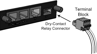
Plugging Terminal block into Dry-Contact Relay Connector
| 3. | Connect the other ends of the dry-contact wires to your external alarm system, according to your requirements. |